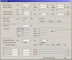
This page details the sections of Region Editor panel that lets you define magnetic regions. Read this to understand the meaning of the textbox values:
Beam geometry
This section defines the location and direction of the beam. Please note that units in SynRad are in centimeters and radians.
Beam start position
The X,Y,Z coordinates of the first point of the beam, ie. where the beam enters the system. Subsequent points will be calculated based on the magnetic field.
Beam start direction
The velocity (direction) vector of the beam in the first point. It will be normalized, so its length has no significance. You can define it by Vx,Vy,Vz coordinates, or by angles. The meaning of angles and the conversion is done the following way:
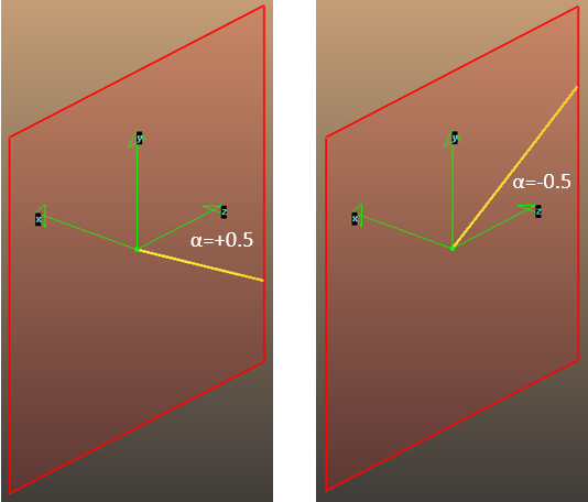
Theta [-PI..PI]: angle with Z axis in XZ plane, positive if X<0

Alpha [-PI/2..PI/2]: angle with XZ plane, positive if Y<0

Conversions:
X=cos(alpha)*sin(-theta)
Y=sin(-alpha)
Z=cos(alpha)*cos(theta)
and
theta0=-atan(Dir.x/Dir.z) [if Dir.z!=0] (as the atan funcion is periodic, for angles outside -PI..PI, a period correction is performed)
alpha0=-asin(|Dir|.y)
Trajectory step lentgh

Calculation boundary

Additional beam parameters section
Ideal beam checkbox
If the beam is ideal, its emittance will be 0. That is, photons will be generated on the trajectory (without any offset), and their direction will be tangent to the trajectory
Non-ideal beam (with constant values)
The emittance, betaX,betaY,Eta,EtaPrime,Coupling and energy spread parameters define how the beam has a nonzero thickness and divergence. That is, each generated photon will have a start loaction offset (perpendicular to the beam direction), and a start direction offset (offset angles relative to the tangent vector).
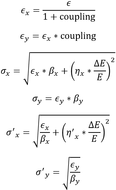
These offsets are calculated by the following:

where dE/E is the energy spread and coupling is the horizontal/vertical beam coupling.
Or by pseudo code:
EmittanceX=Emittance/(1+Coupling)
EmittanceY=EmittanceX*Coupling
sigmaX=sqrt(EmittanceX*BetaX+Sqr(Eta*Energy_spread))            { hor lattice-dependent beam dimension, cm }
sigmay=sqrt(EmittanceY*BetaY)                                   { same for vertical, cm }
sigmaXprime=sqrt(EmittanceX/BetaX+Sqr(EtaPrime*Energy_spread))  { hor lattice-dependent divergence, radians }
sigmaYprime=sqrt(EmittanceY/BetaY)                              { same for vertical divergence, radians }
x_offset=Gaussian(sigmaX)                                       {starting point X offset, gaussian distribution with SigmaX st.dev.}
y_offset=Gaussian(sigmaY)                                       {starting point Y offset, gaussian distribution with SigmaY st.dev.}
divx_offset=Gaussian(sigmaXprime)                               {starting direction alpha offset, gaussian distribution with sigmaXprime st.dev.}
divy_offset=Gaussian(sigmaYprime)                               {starting direction theta offset, gaussian distribution with sigmaYprime st.dev.}
Watch out for units: all quantities containing distances (Emittance, BetaX, BetaY and EtaX) are in centimeters, whereas EtaXrime is dimensionless. The coupling is in percents.
Non-ideal beam (BXY file)
The BetaX, BetaY, Eta, EtaPrime and Energy-Spread parameters above can vary with the coordinates. In such a scenario, use a BXY file.
Photon generation
Generated photon energy
Spectrum plotting, etc. require a scale of energy values that generated photons can have. You can limit this range between two values
Polarization mode
If you want to see two different results for parallel-only or orthogonal-only polarizations, uncheck one of the toggles.
Limit photon divergence
If, for some reason, you want to limit the maximum divergence angles, set a value here, and photons with larger angles will be omitted
Magnetic field
Define the magnetic field here, independently for the Bx, By, Bz components. Eiher use constant values (in Tesla), or choose one of the seven magnetic modes and a MAG file.
