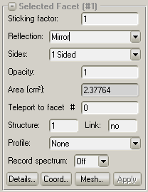
Sticking factor: The probability (between 0 and 1) that an incident photon will be absorbed on the selected facet(s).
Reflection:
Diffuse: the reflected photon will be leaving the surface with phi angle with cos(phi) probability (Lambertian radiator)
Mirror: the reflected photon will leave the surface with the incident angle
Material (copper, aluminium, Al2O3): The reflection probability (1-sticking_factor) depends on the photon's energy and incident angle according to the following eperimental data. Forward- and backscattering is optionally supported, and you can define material reflection tables yourself (CSV files in the parameters directory)
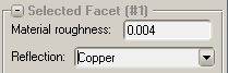
Roughness:
You can optionally enable rough surface scattering.
In Tools / Global Settings, you can choose between the old and new reflection models.
In the old (default) reflection model, reflection is specular (mirror-like), but as surface roughness is taken into account, the theta and phi angles (between the reflected direction and the surface normal) are perturbated with a gaussian distributied offset:
thetaOffset=atan(sigmaRatio*tan(PI*(rnd()-0.5)));
phiOffset=atan(sigmaRatio*tan(PI*(rnd()-0.5)));
Sides: One sided facets are transparent from their back (back is the opposite side of where the normal vector is pointing), while 2-sided facets are opaque from both sides. In SR applications, 2-sided facets might always work.
Opacity: The probability that a photon will interact with the facet. (If opacity and sticking factor are both 0.5, the facet will let through 50% of incident photons, reflect 25% and absorb 25%).
Teleport: You can "teleport" photons, a function you might want to use for systems with periodic boundary conditions. See the relevant help section for Molflow to learn to set the up.
Structures: Identically to Molflow, you can speed up the simulation by dividing the structure into smaller structures. Not really used.
Profile: if enabled, the facet will be divided into 100 slices along their local U or V vector, and flux and power will be calculated for each slice. Use Tools/Profile Plotter to visualize the curves.
Record spectrum: for speed and memory reasons, the spectrum of absorbed photons are calulcated only for facets where you enable this feature. If you enable it, use Tools/Spectrum plotter to visualize it.
Mesh button: will pop up the Facet Mesh dialog where you can create textures:
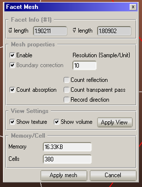
To add a texture to the selected facet(s), tick Enable, tick the absorbed (or reflected) mode, and set resolution. Resolution is in samples/cm, so if the resolution is 10, each texture cell will be 0.1cm*0.1cm.
The view settings panel allows you to make the volume and texture display of selected facets transparent (without stopping the simulation).
[1] GF Dugan, KG Sonnad, R Cimino, T Ishibashi, and F Sch¨afers. Measurements of x-ray scattering from accelerator vacuum chamber surfaces, and comparison with an analytical model. Physical Review Special Topics-Accelerators and Beams, 18(4):040704, 2015.