Recently two MolFlow users have been facing a similar problem:
One of them wanted to simulate outgassing due to beam loss, others had outgassing due to electrons in the system. In both cases, they had a distribution of outgassing that changed depending on the location. The only way to enter it to MolFlow was to create a matrix of facets, and define the outgassing rate one-by-one. A rather long and boring process.
So I decided to create a way of defining a spacial outgassing distribution. The key is the Explode command that existed already in Molflow.
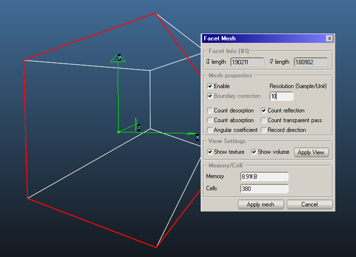
First, you have to define how fine the outgassing matrix is by defining a regular mesh:
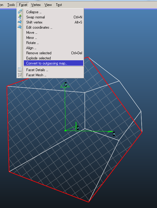
Then we select the facet and issue the new "create outgassing map" command:
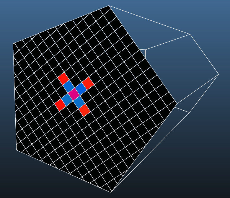
Below you see a map of the facet. For each mesh element, you can manually set the outgassing value. Note that the edited cell's location is highlighted on the geometry (similar to texture plotter):
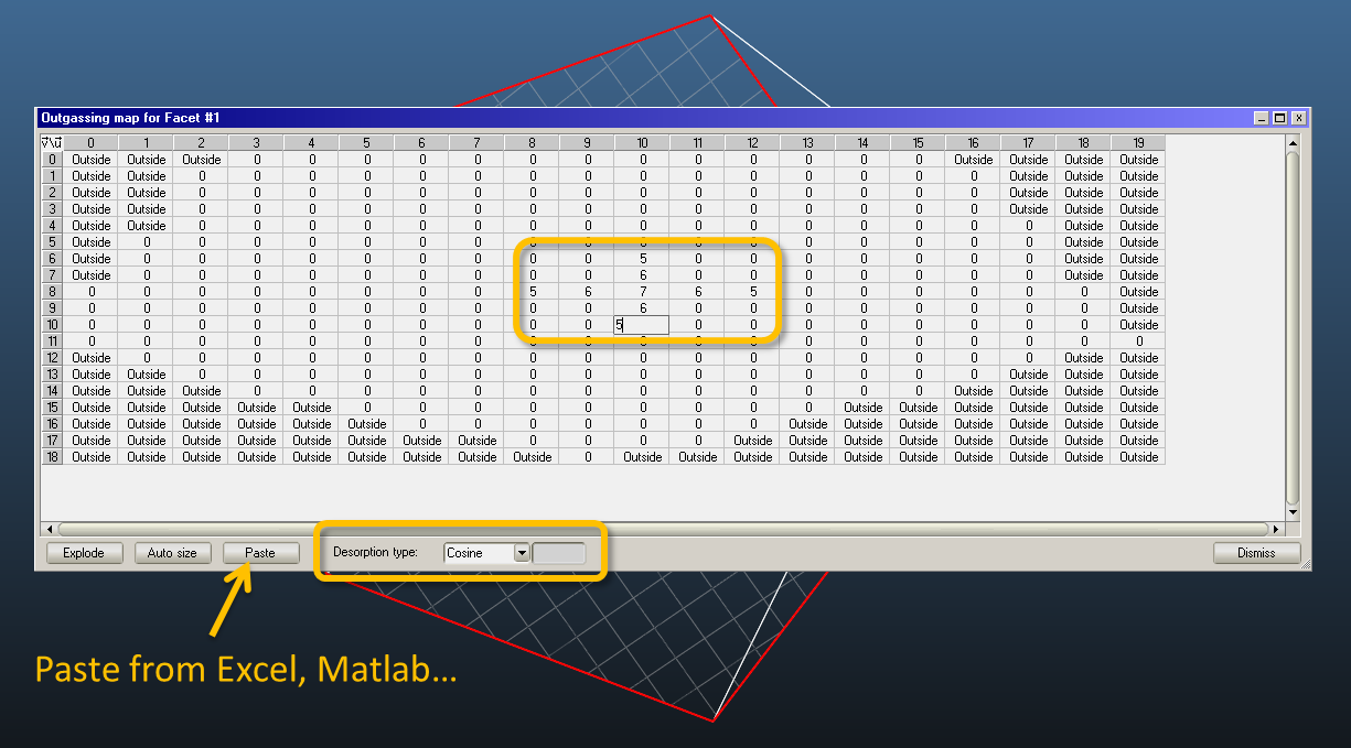
(Click image to magnify)
You can also paste values from the clipboard from Excel. The values are pasted to the right and bottom from the actual cell. Then you can define the desorption type (Uniform, Cosine, Cosine^N). Finally, if everything's ready, click Explode.
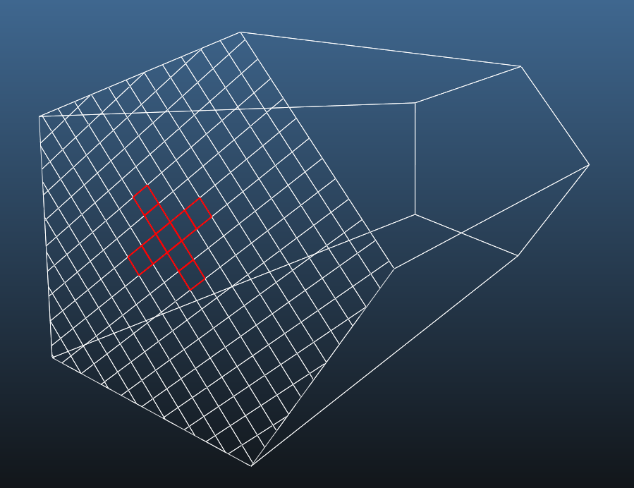
The exploded geometry highlights those facets that have a desorption now:
To test that everything was well defined, add a mesh that counts desorbed molecules, and you'll see a nice colormap of the values you just entered:
That wasn't hard, was it? Happy outgassing! ;)